Touch ID Trackpad build
*Last updated: 13th December 2025*
I built this Hidden Touch ID for Apple Magic Trackpad.
From the project page:
Touch ID is super convenient when using macOS, but it is restricted to Apple keyboards and those are not really something I enjoy or want to keep on my desk. SnazzyLabs’ standalone Touch ID module inspired me to build something similar, yet I wanted to avoid having an additional box on my desk. So I set out to seamlessly attach the Touch ID button to something that’s always sitting on my desk: Apple’s Magic Trackpad.
The idea is to transplant the Touch ID button from an Apple Magic Keyboard into a 3D-printed case which augments an Apple Magic Trackpad. This gives easier access to a Touch ID button. In my case, my main computer is a Macbook Pro which sits on a monitor arm off the desk which makes accessing the Touch ID on the Macbook annoying. The idea of this is to bring it within reach.
These are the steps I followed to complete the project.
Prerequisites
Before I started I needed a few things.
-
Donor keyboard, I used Apple Magic Keyboard with Touch ID USB-C version (model A3118) acquired from eBay. It was Swedish language, which made it slightly cheaper on the UK eBay.
(In fact, it ended up being free due to eBay/Evri incompetence – sweet.)
-
A T-3 screw driver bit for the screws.
-
Various spudgers and prying tools for keyboard disassembly.
-
A 3D printed case made of various pieces – see below.
-
And, of course, an Apple Trackpad. Mine was a version 3.
3D printing the case
My original plan was to get this printed by a friend or use a service like PCBWay, but I had acquired a 3D printer by the time I needed it, so I ended up printing it myself.
I printed the case on my Bambu A1 using the Bambu Basic PLA in Gray (10103). This was one of my first ever 3D prints, so I don’t know how well it will last, but it looks pretty good.
These are the STL files I used for the print. See the full list on the project page.
- Trackpad3_Touch_ID_body_USB-C_v2.stl
- Trackpad3_Touch_ID_lid_v2.stl
- Trackpad_Touch_ID_clickplate_v2.stl
- Trackpad_Touch_ID_clickplate_simple_v2.stl
- Trackpad_Touch_ID_keycap_v2.stl
- Trackpad_Touch_ID_wedge_v2.stl
The project author supplies two different click plates (this is where the Touch ID button will attach later) – one has a slot for the gasket cylinder from the keyboard which apparently makes the button clickier. I printed both because I wasn’t sure which one I was going to go with and they are small pieces, so I was willing to spend the filament to try both.
After printing I ended up with these parts.
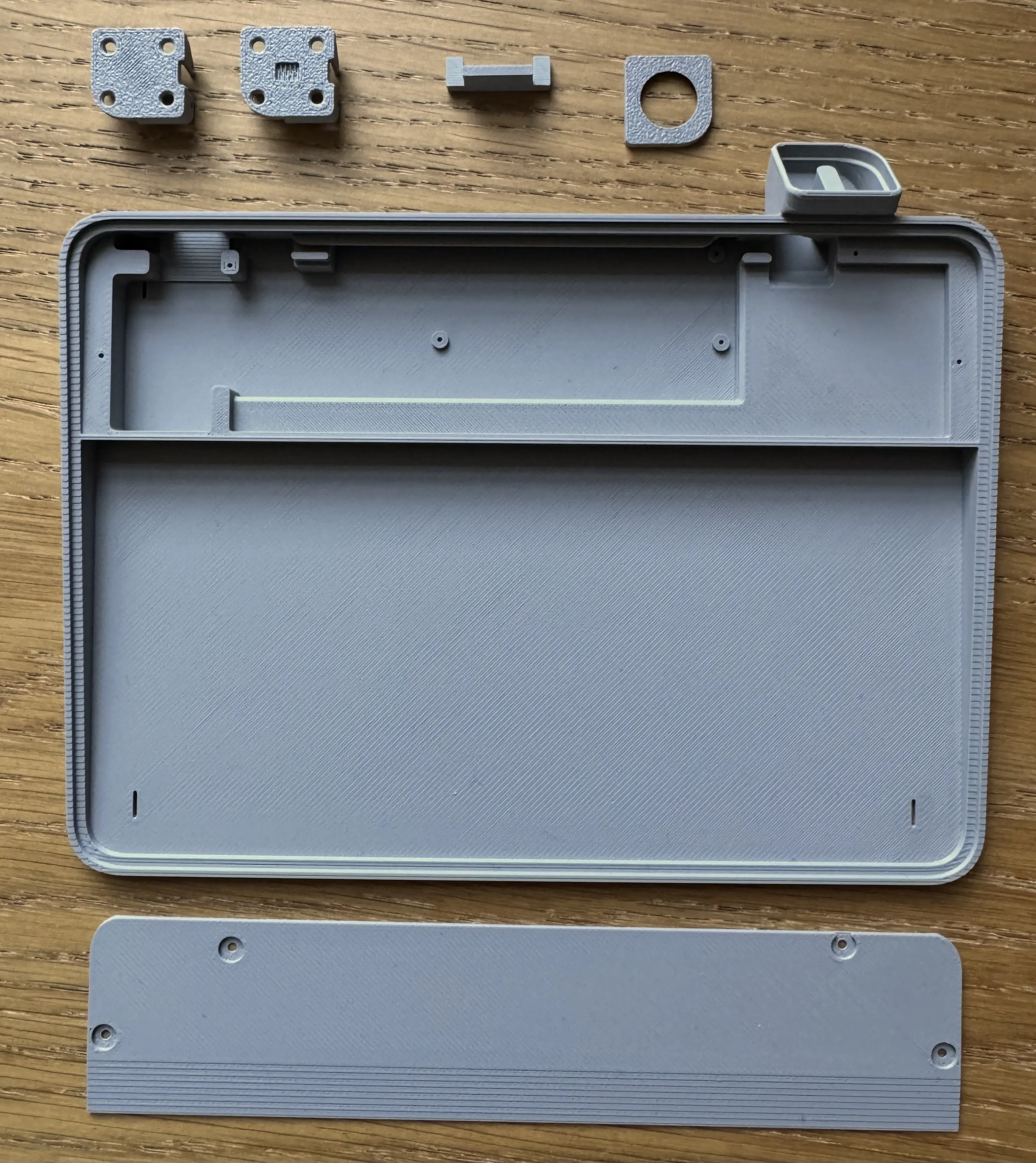
Donor keyboard disassembly
Before putting everything together I had to disassemble the donor keyboard to harvest all the bits and pieces. I don’t have photos of the keyboard disassembly unfortunately because I forgot to take them. Let’s just say that that keyboard is no more. It has ceased to be. I would thank it for it’s service, but I never used it.
Here is a disassembly guide, which I failed to follow, but that you might find useful.
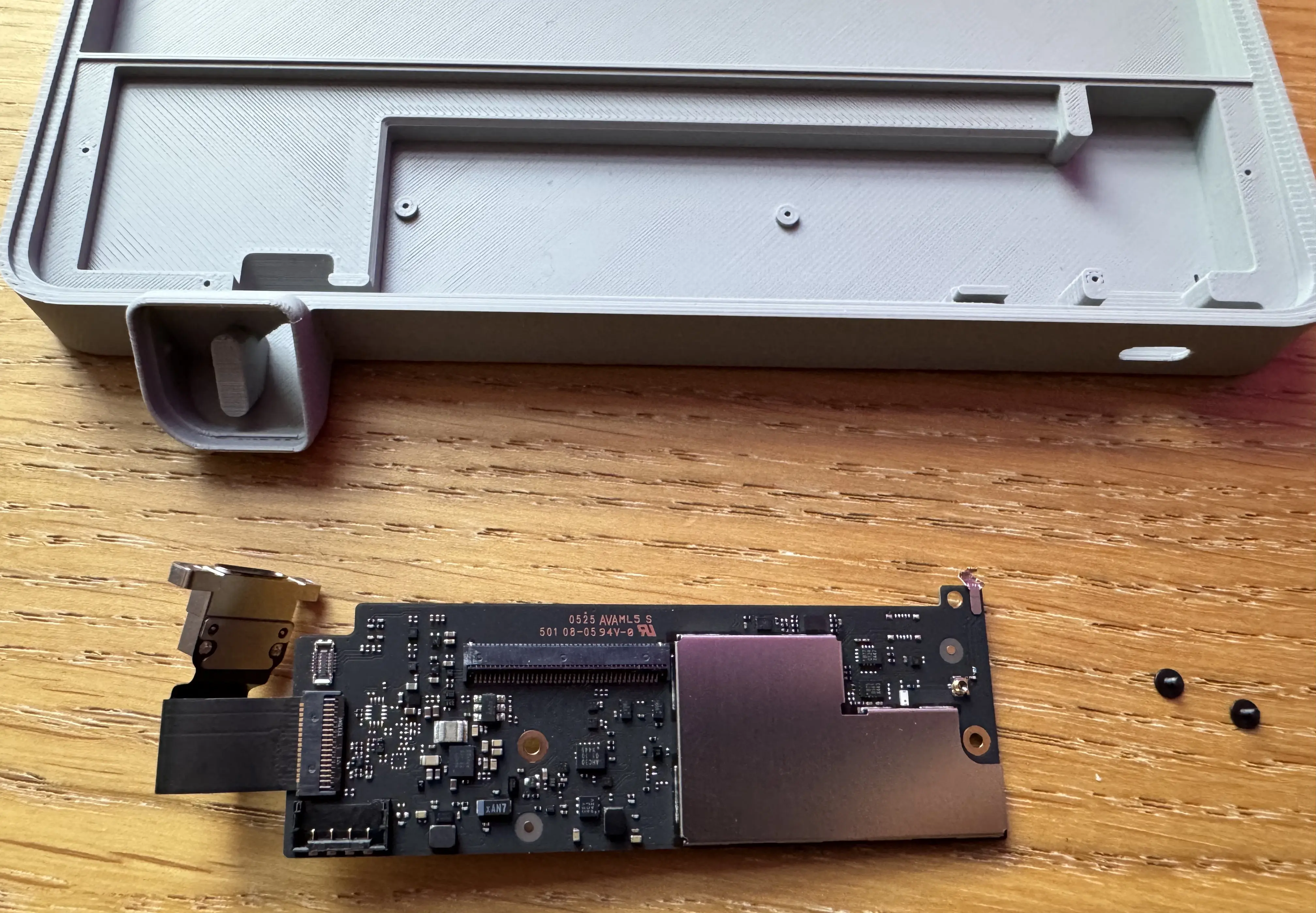
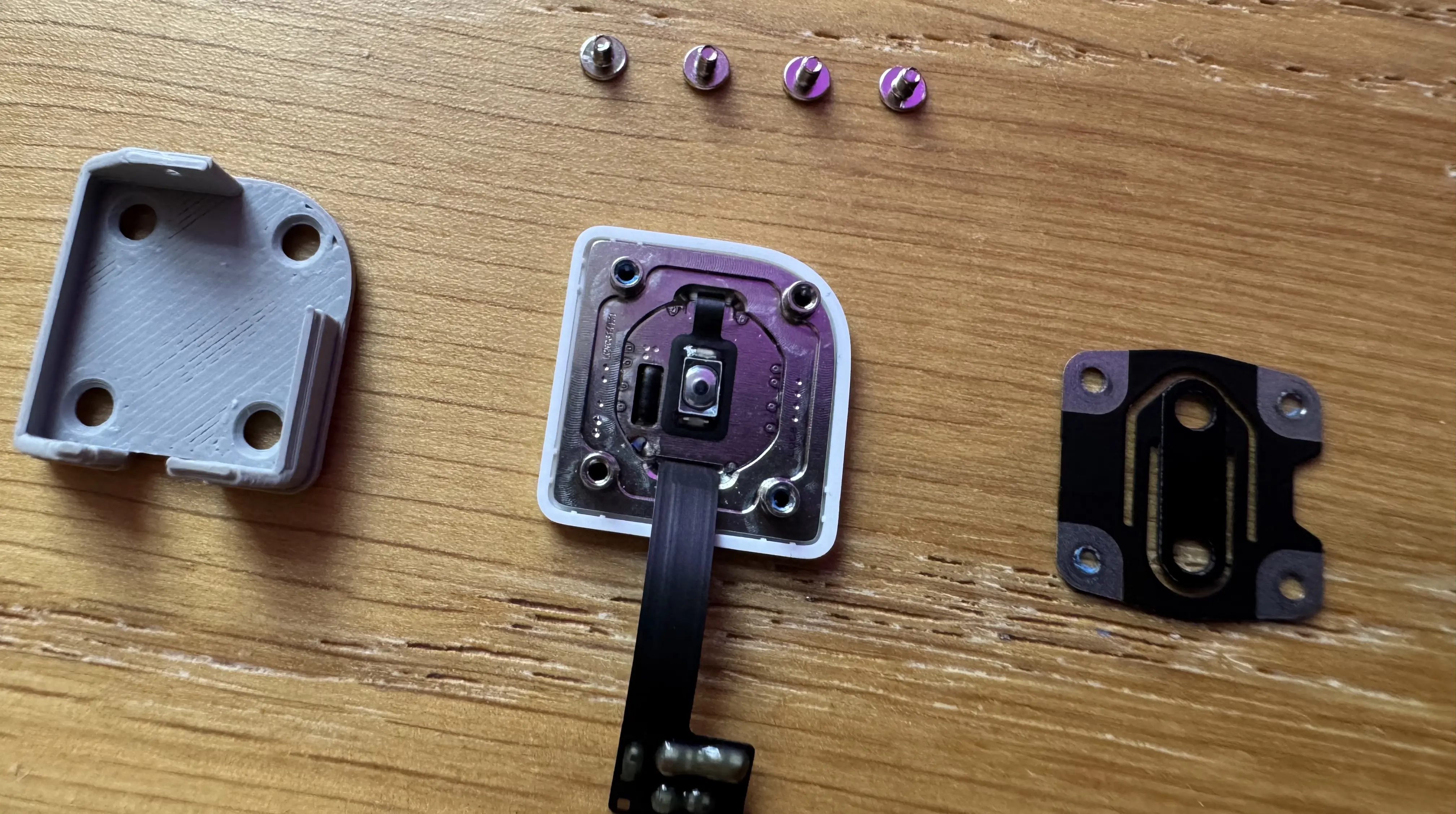
Here are all the pieces I ended up with.
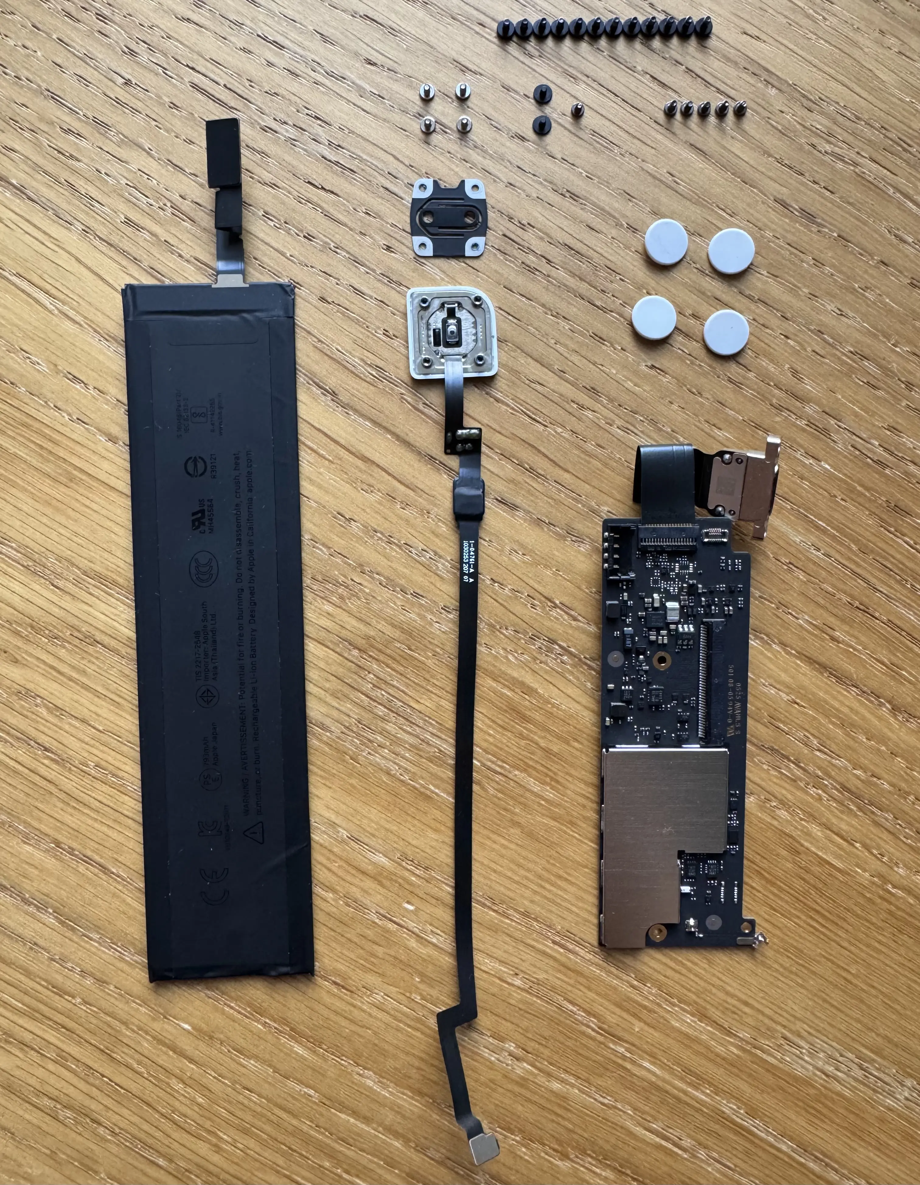
I wasn’t sure which screws I’d need, but there were far more than are required for this build, so I just kept them all just in case.
The build
The steps I follow here are more or less the same as the “official” instructions, but show exactly what I did.
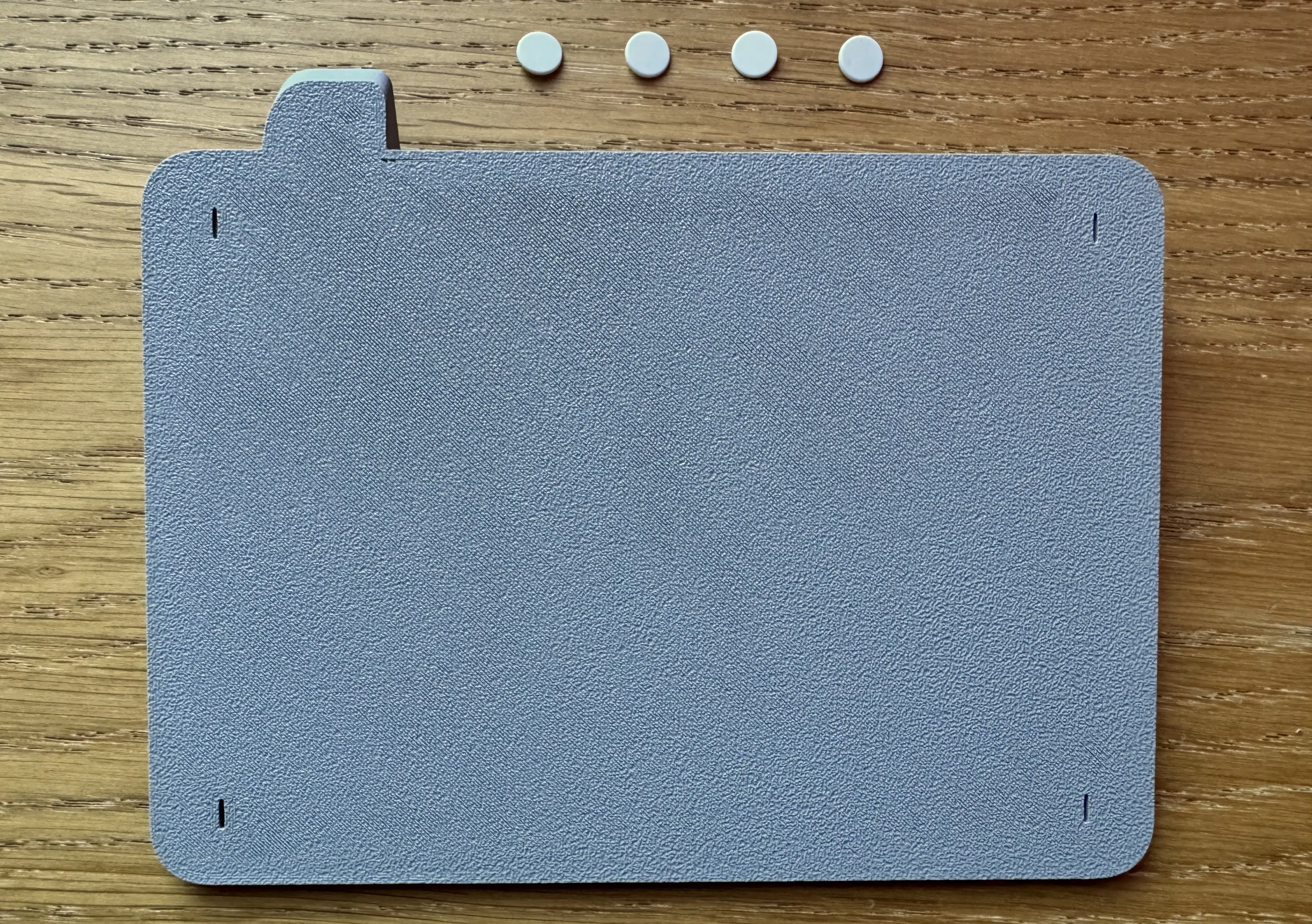
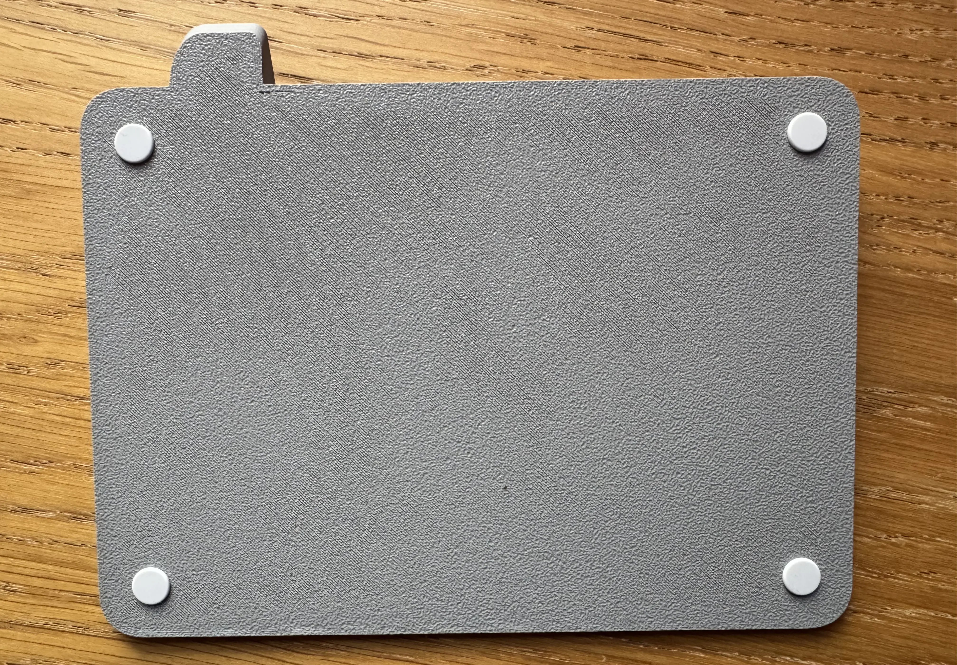
First things, first. I attached the feet to the main case. The feet have small tabs that fit into slots on the base so lining them up is straightforward enough, if not a bit fiddly. I used a dab of super glue too.
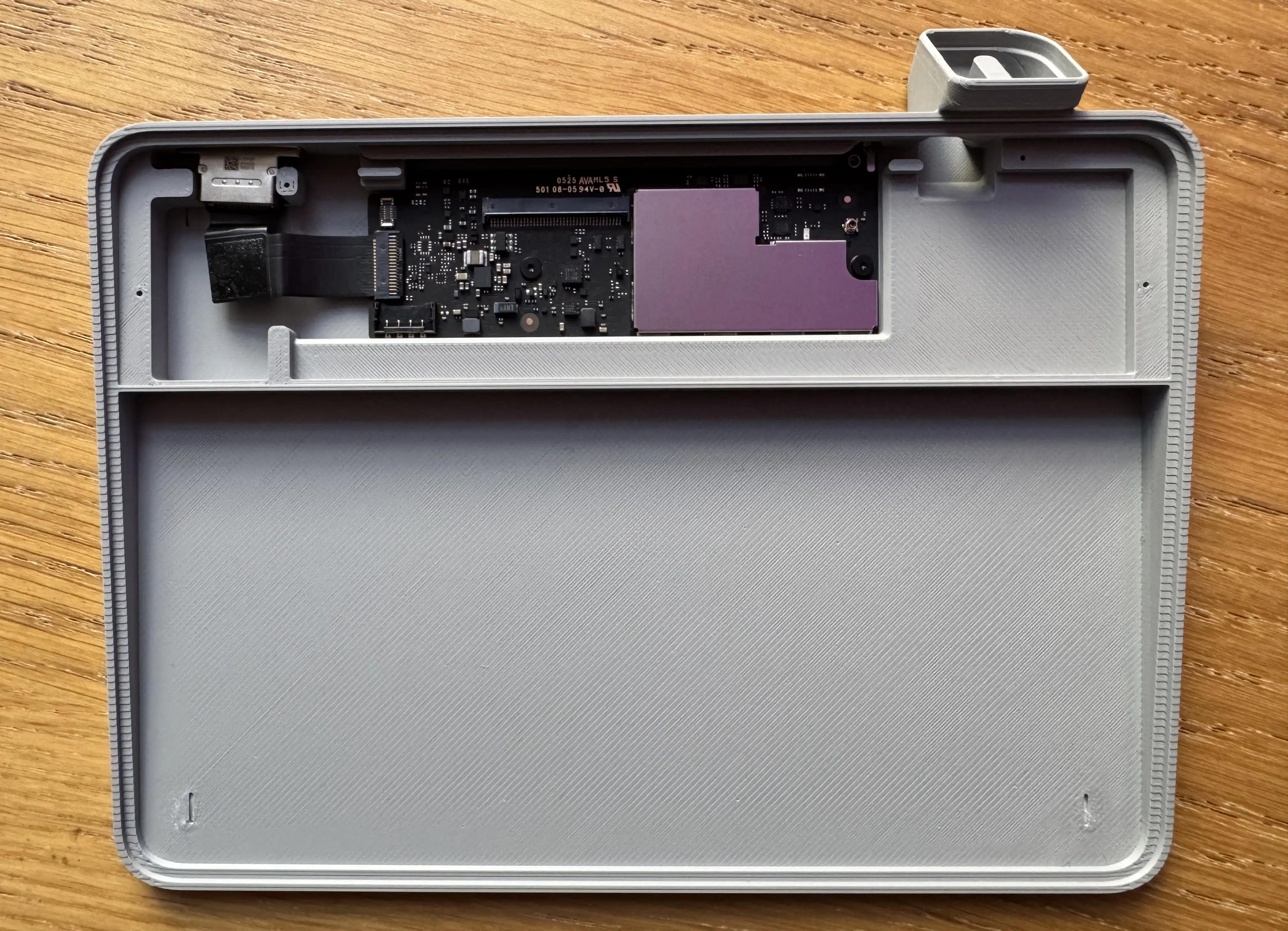
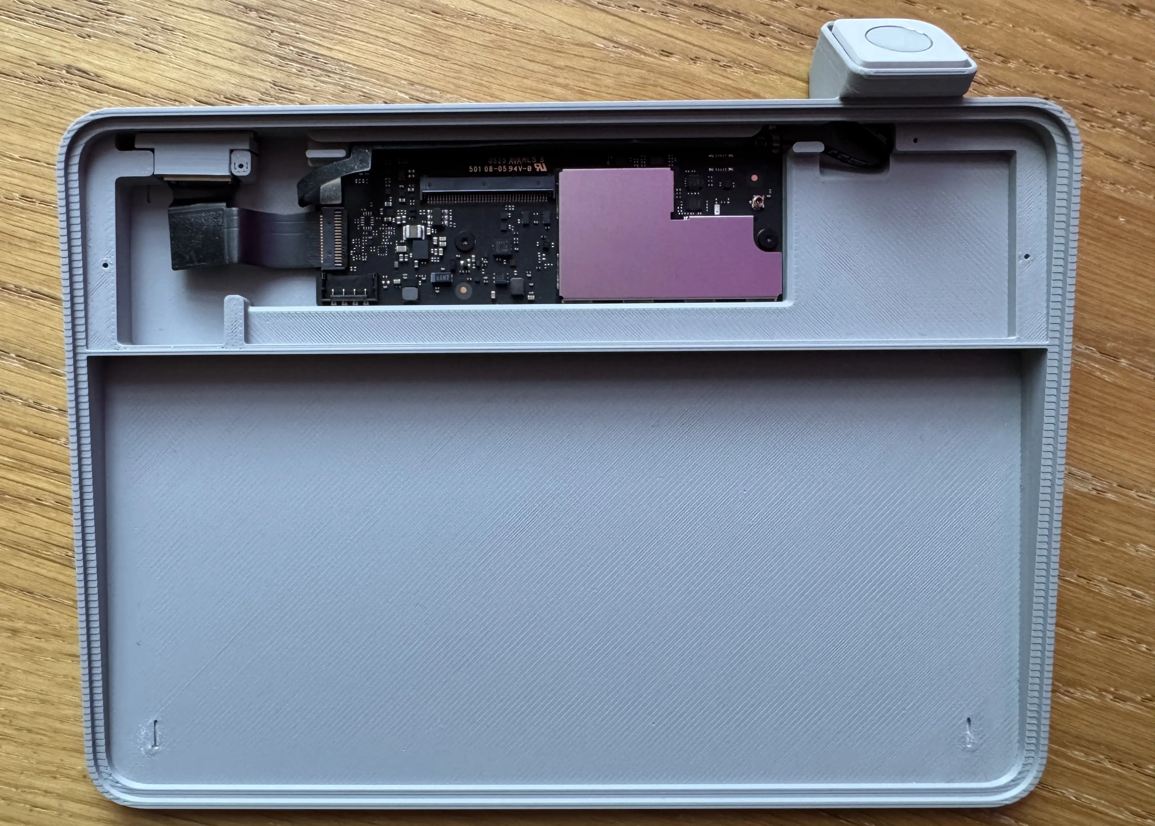
Next I put the keyboard PCB into the case and screwed it down using some of the larger screws. The screws are self-tapping as the original instructions said, but were slightly tricky to get going. A bit of firm pressure got them in place.
As I said before, I wasn’t sure which clickplate to use. I opted for the non-simple version in the end (Trackpad_Touch_ID_clickplate_v2.stl) and had to super glue the gasket cylinder into the small cut-out.
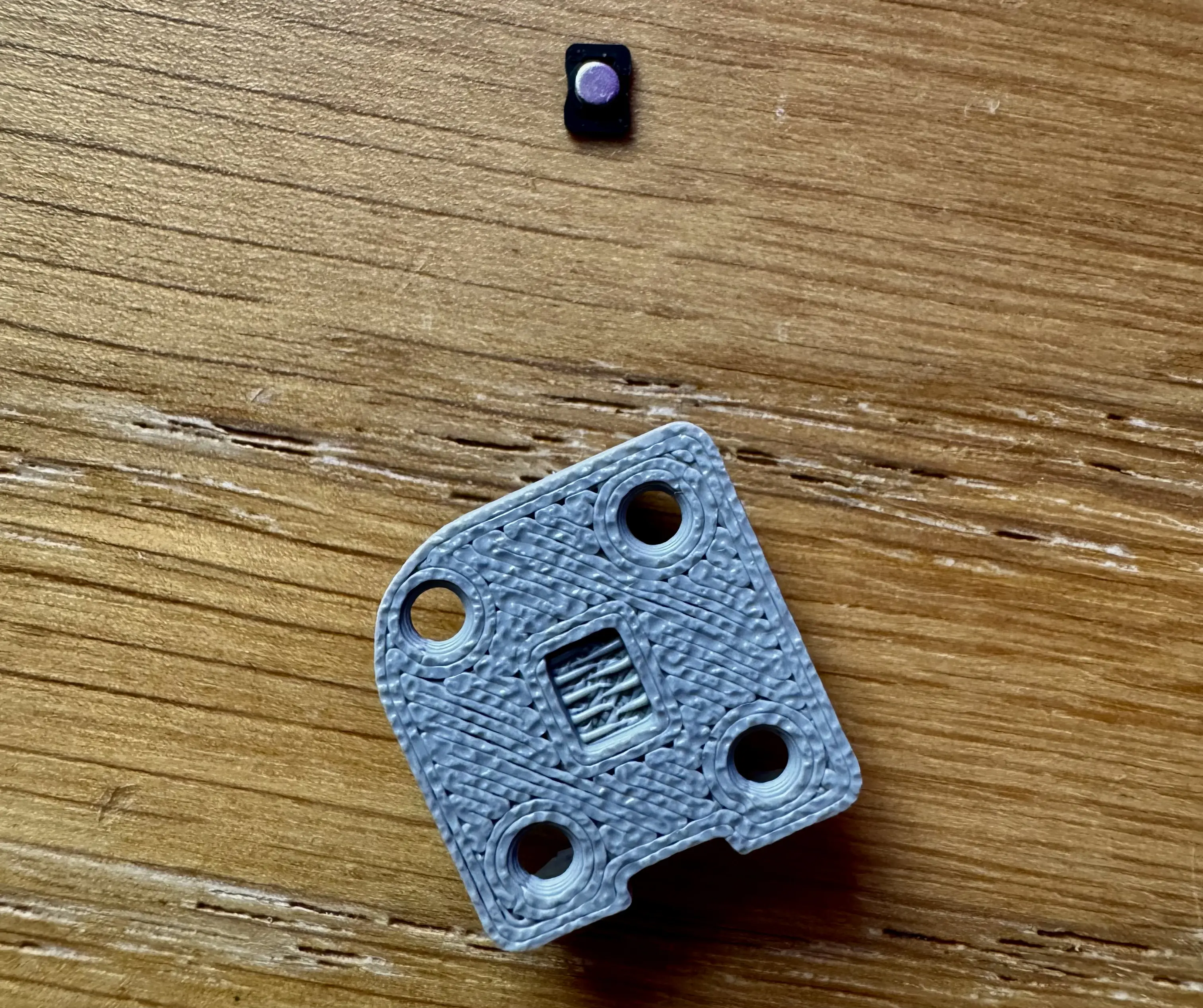
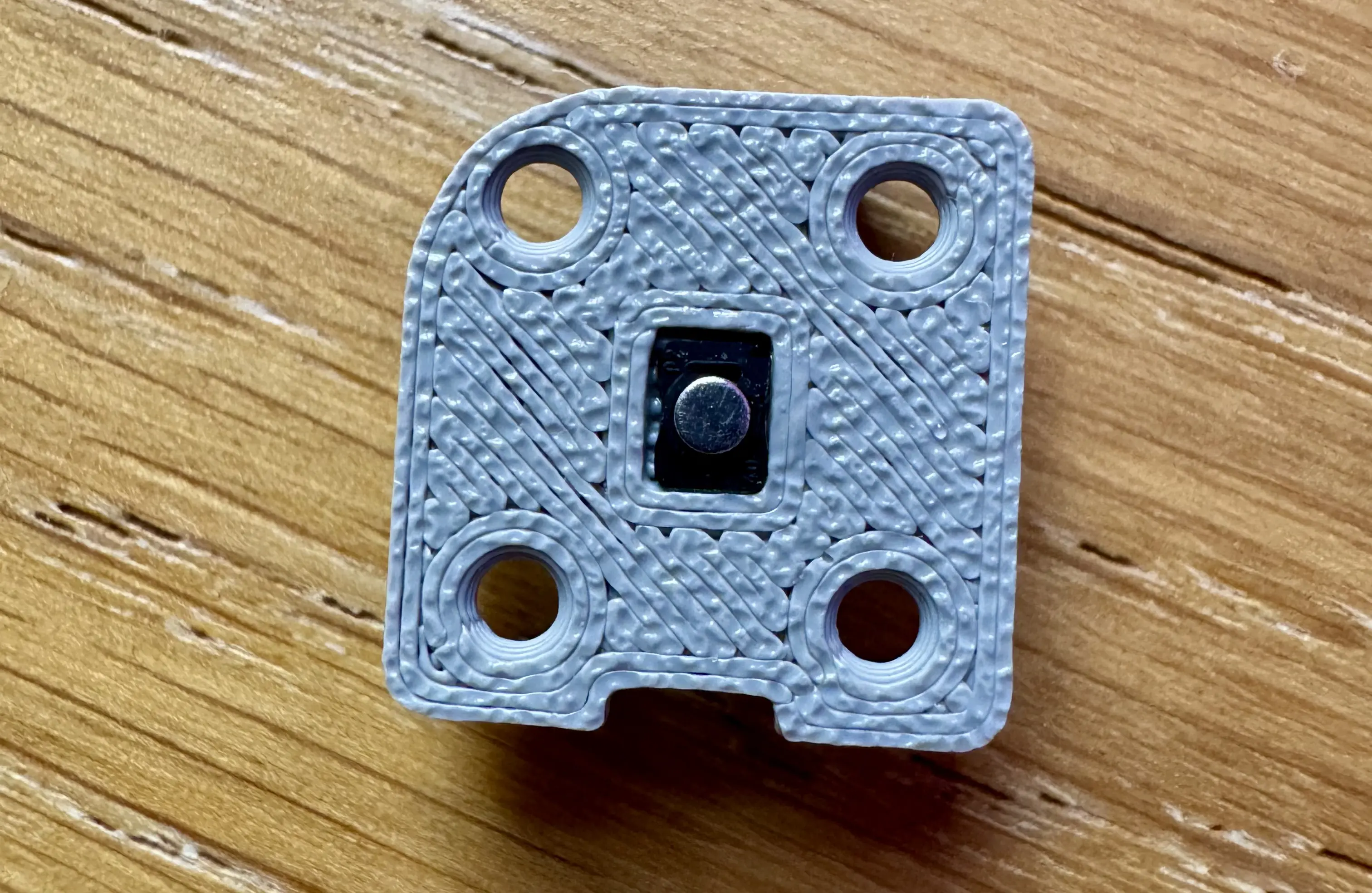
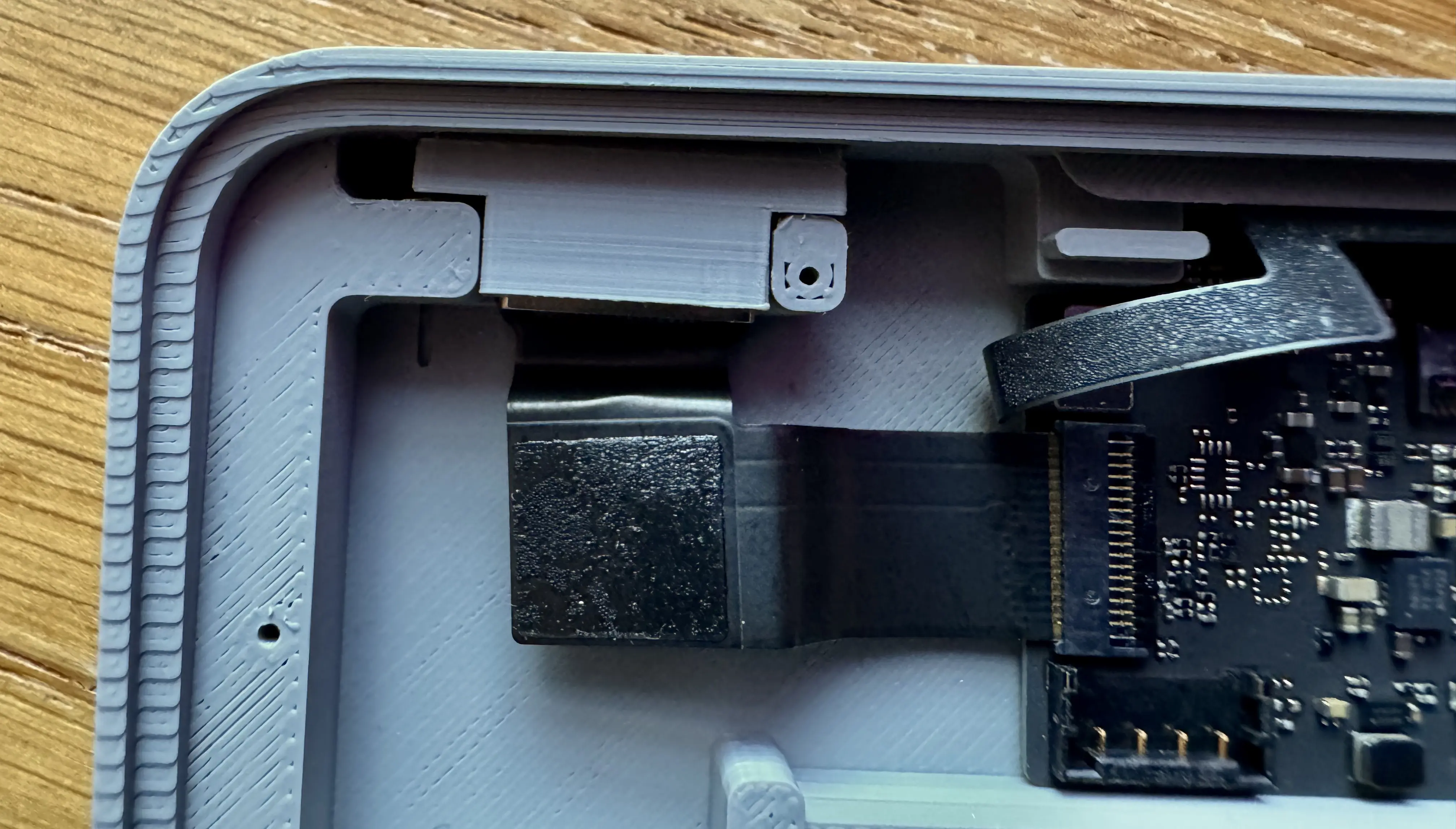
Then I moved onto the Touch ID sensor/button itself. The button needed to be mounted into the mounting plate. The mounting plate then pushes into the main case. The button orientation was made clear by the rounded corners on both the button and case part.
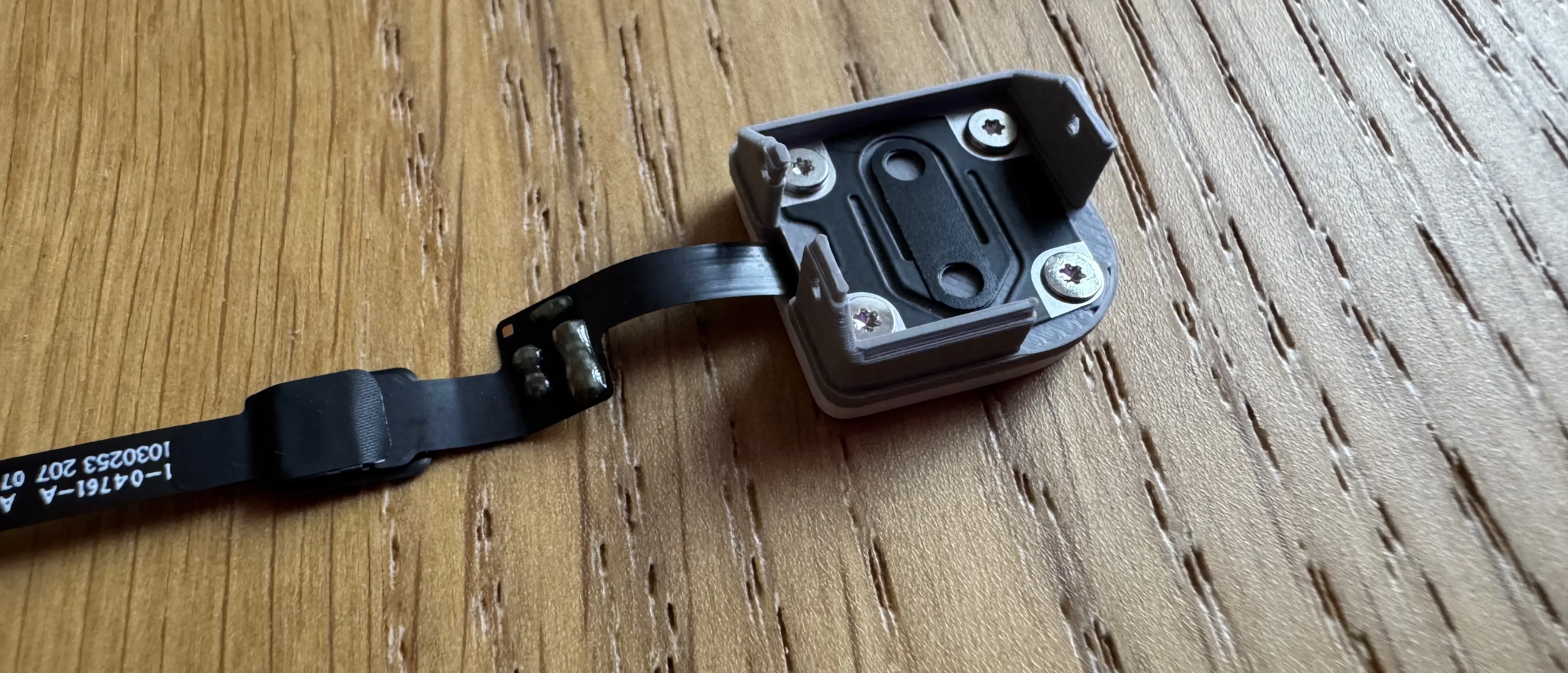
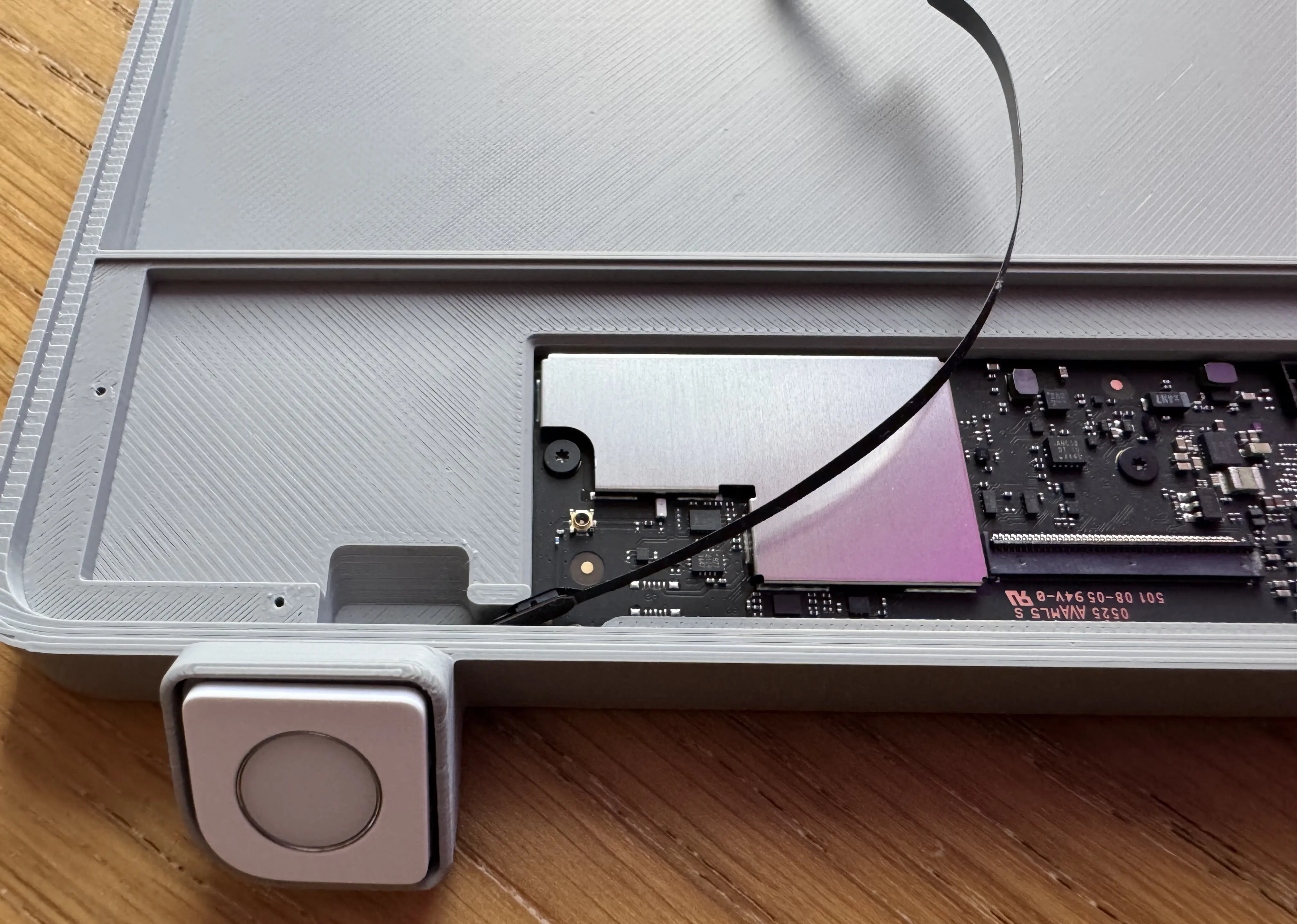
Now I could put the whole assembly in place. The flex cable went through the slot by button and was then thread up along the top next to the PCB. The cable seemed resilient enough, but I was careful to not bend it too much. I then connected it to the PCB. Finally, I clicked the mounting plate into the button slot.
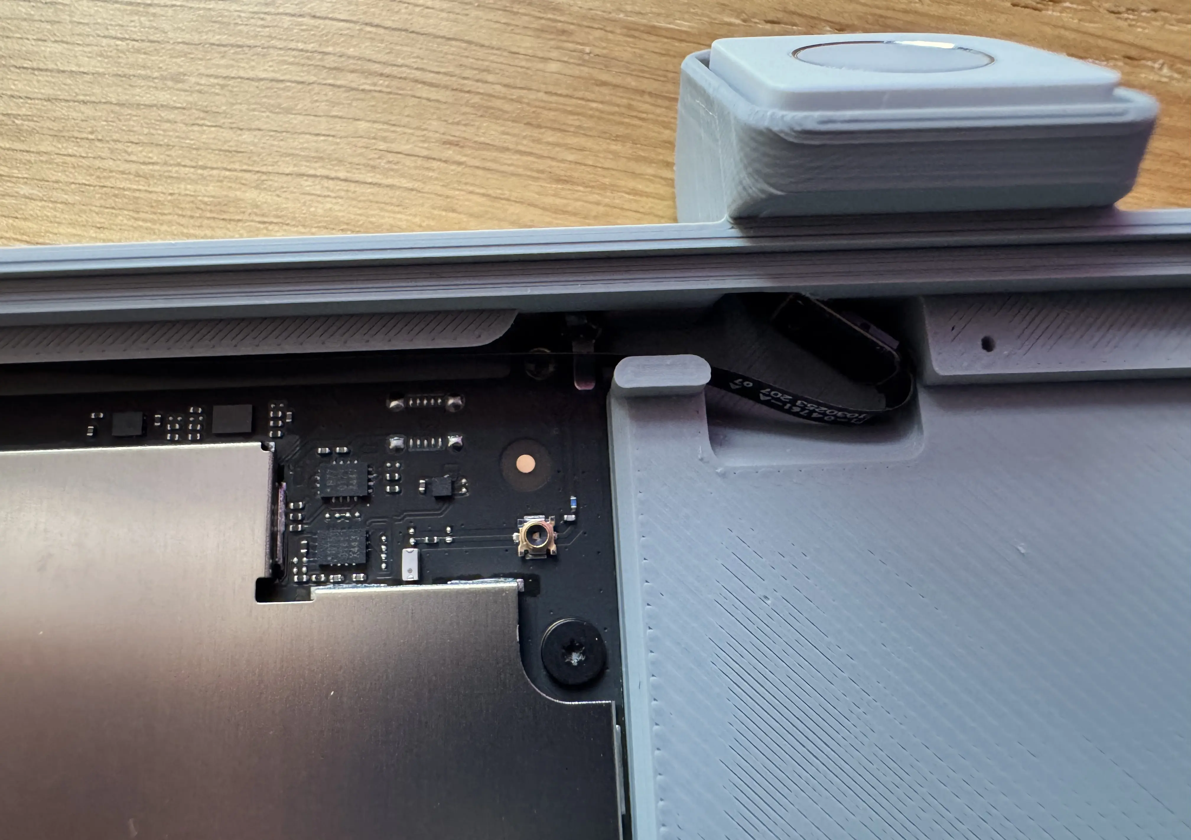
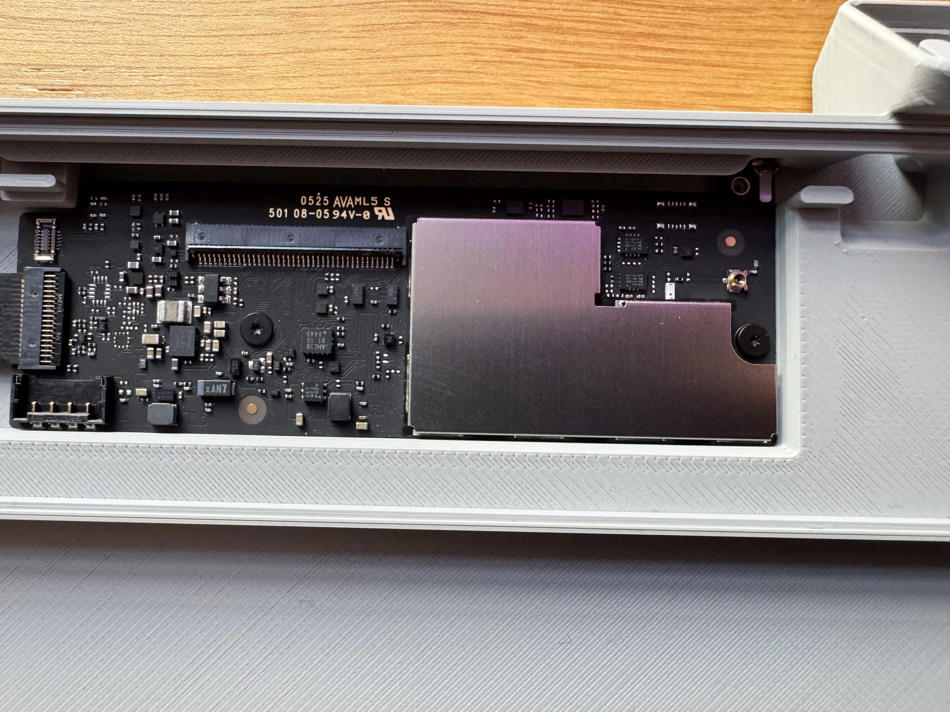
The USB-C connector was still flapping about at this point, but inserting the
“wedge” (Trackpad_Touch_ID_wedge_v2.stl) easily secured it and stopped it
moving. I was surprised at how well this worked because I couldn’t work out the
orientation at first. It pushes in from above.
This was probably the trickiest part of the whole process.
Sliding the battery was easy, but I couldn’t work out how to connect the battery to the PCB and I hadn’t been observant enough during the keyboard disassembly to recall how it fitted.
Turns out that the battery flex cable pushed straight down onto the PCB connector. It made a positive click.
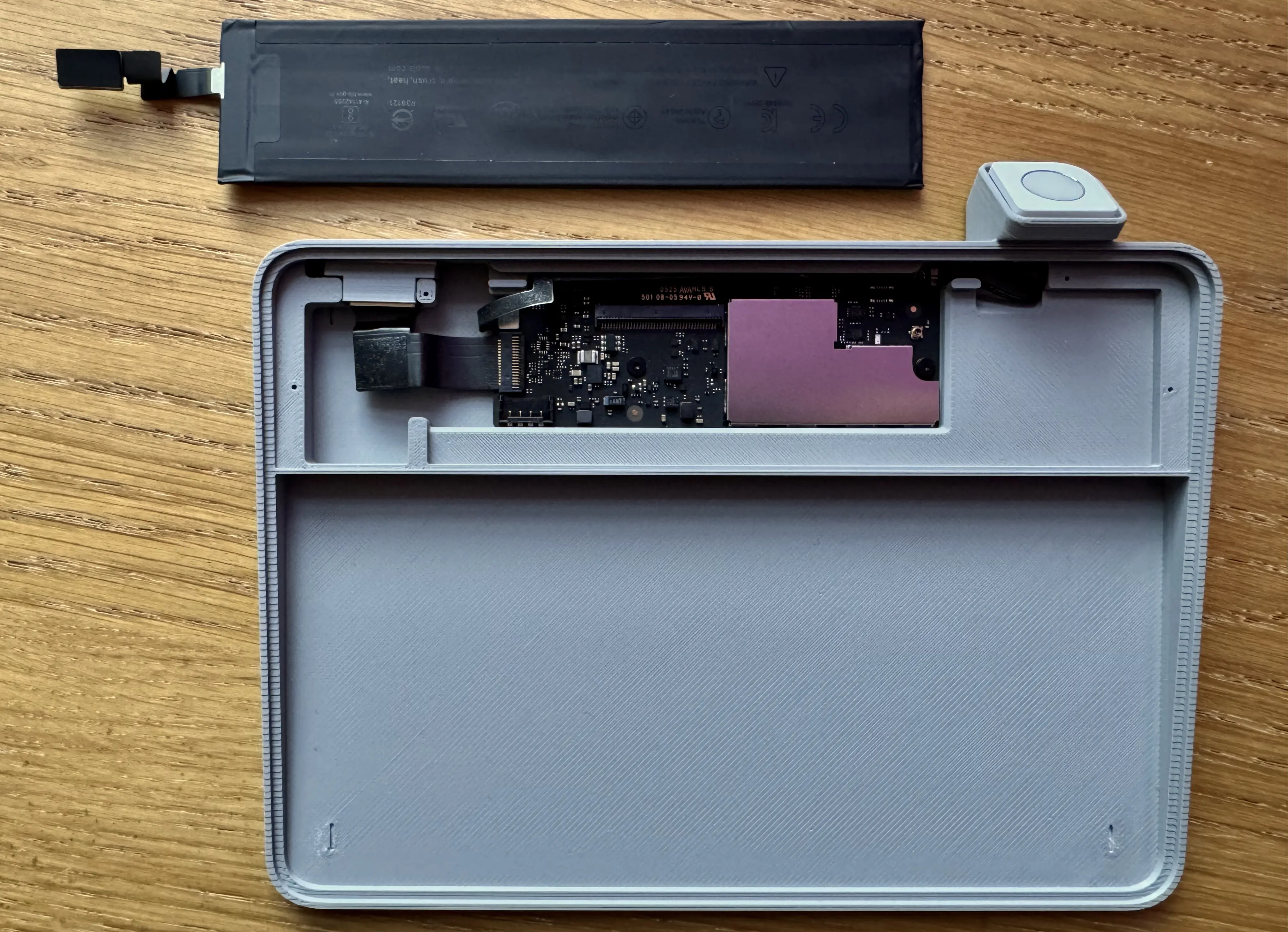
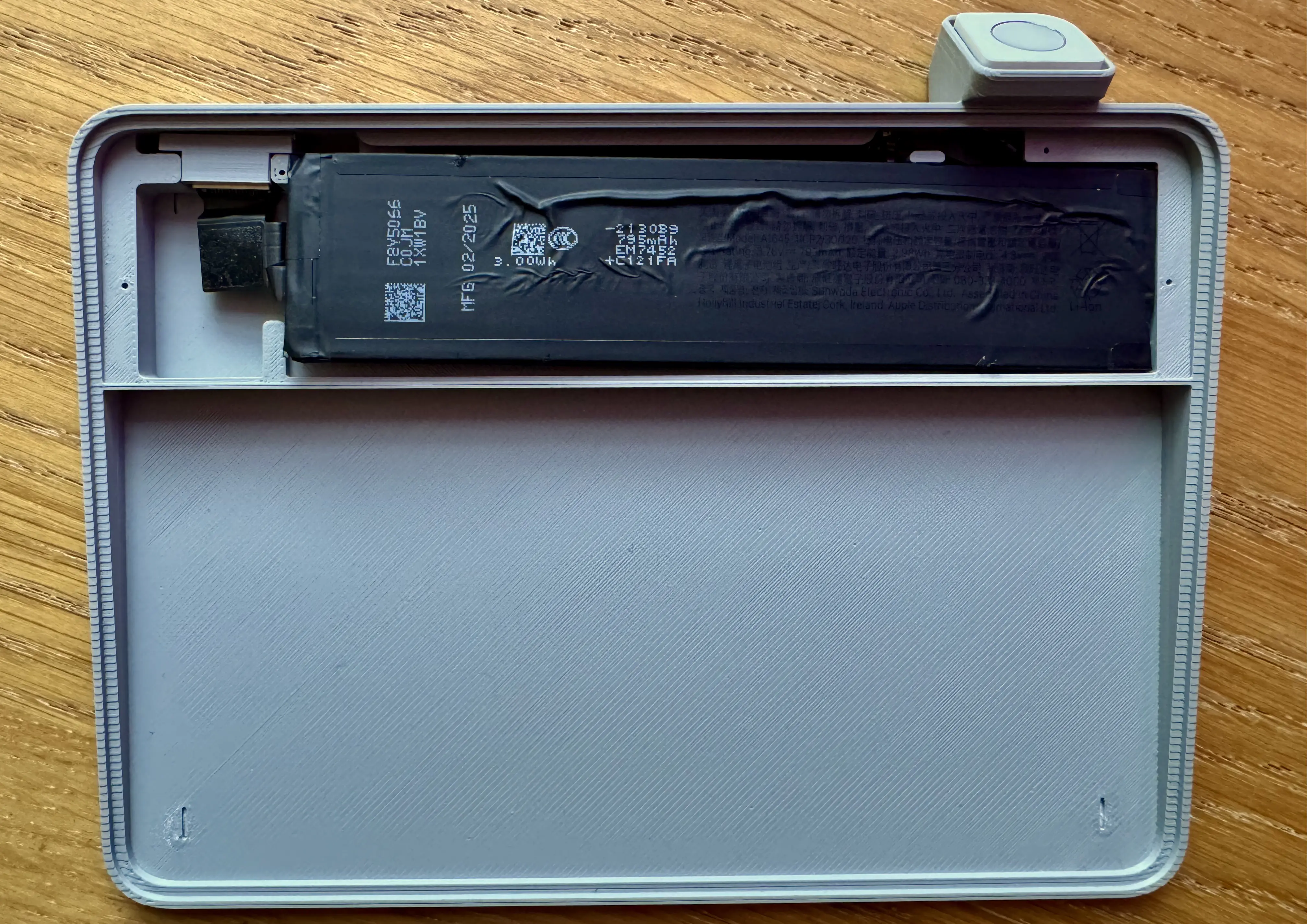
Now I just had to close it all up. I slide the lid on over the battery and screwed it in. Again the screws are bit fiddly. Half the battle was getting the screws to stay on the screwdriver whilst I put them in.
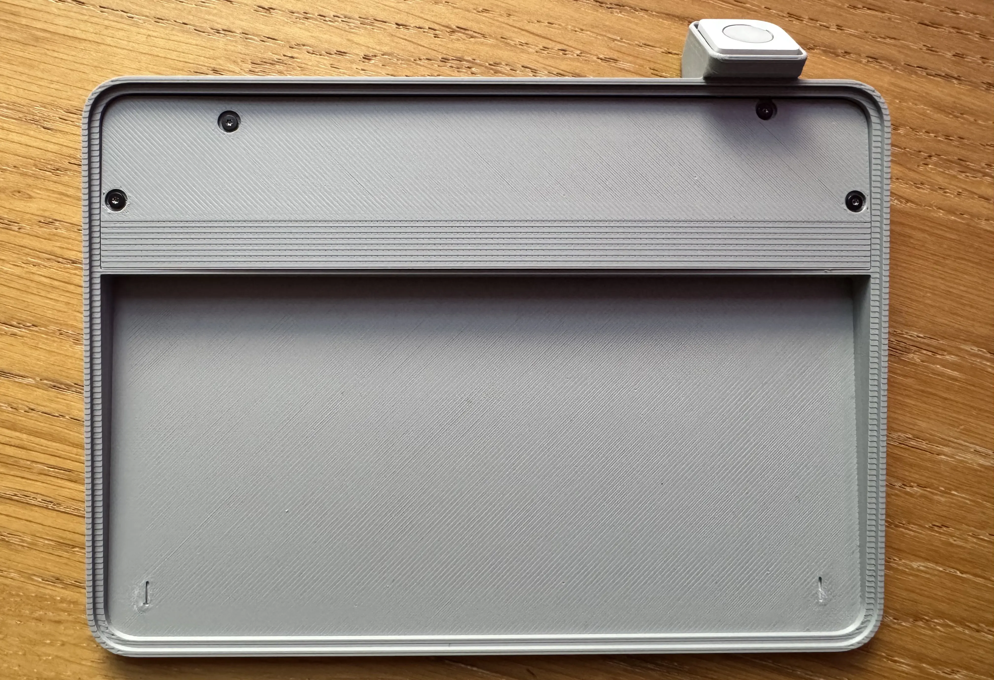
Slide in the Apple Trackpad. Profit!
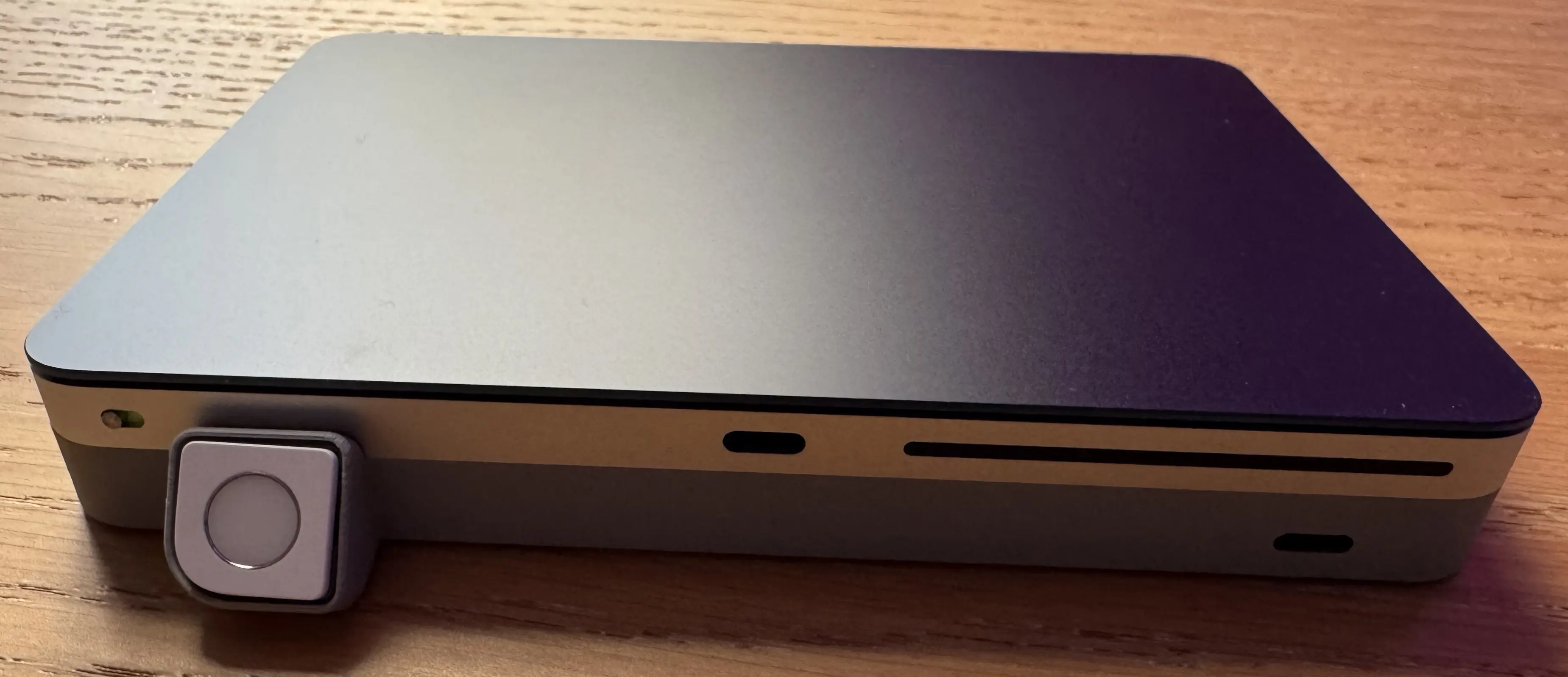
Not too bad at all.